A QCTP was purchased for the lathe. It comes with a generic steel base plate that is 0.473" X 1.844" X 2.359". The South Bend lathe compound has a T-slot that is 1.295" wide at the bottom and 0.880" wide at the neck. Both the neck and the bottom are 0.280" high. The current base plate holding the lantern tool post in place is 0.250" X 1.250". The photo shows the difference.
This base plate could be machined to the correct size for the T-slot or a new plate could be made. One issue keeping me from making a new plate is the screw. The base plate is screwed through the QCTP to a nut on top. So far this screw has defied identification. The screw is 0.543" in diameter. It is close to 18 TPI, so it could be a 9/16-18 thread, but should be 0.563" in diameter. A metric 14 screw would be a closer 0.551" in diameter. A standard M14 would have either a 2 mm pitch (12 TPI) or a 1.5 mm pitch (16 TPI). It is not easy to find nuts in fine threads either inch or metric. I will explore machining the included base plate first.
Turning the included base plate into one that fits the T-slot will take three operations. First the plate needs to be reduced to 0.425" or so. If it is too thick, when tightened it will hit the bottom of the QCTP. The second operation needs to narrow the width of the block from the current 1.844" to 1.25". This needs to happen equally on both sides to keep the screw hole centered. 0.297" needs to be milled off of both sides. Third the shoulders need to be cut. These will be 0.175" deep from the top and 0.20" in from the sides. The first two operations can be done on the South Bend using the new DRO.
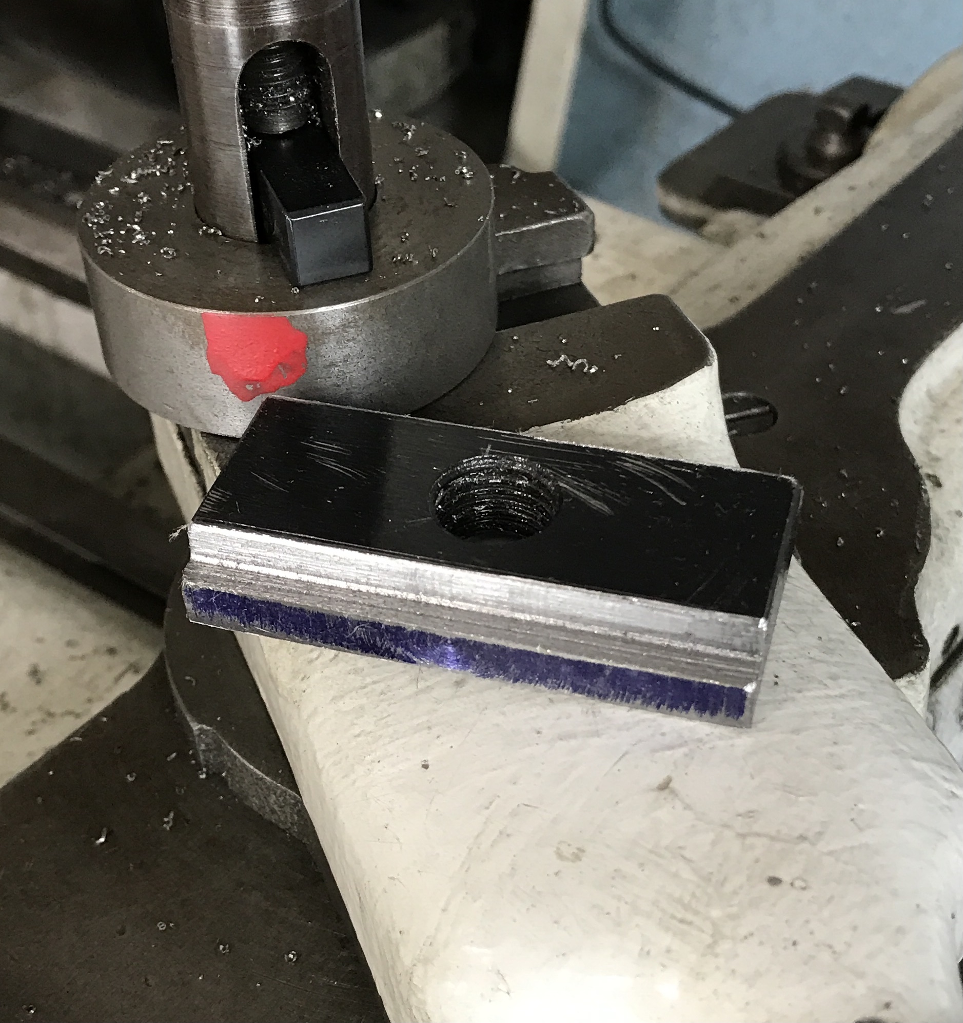
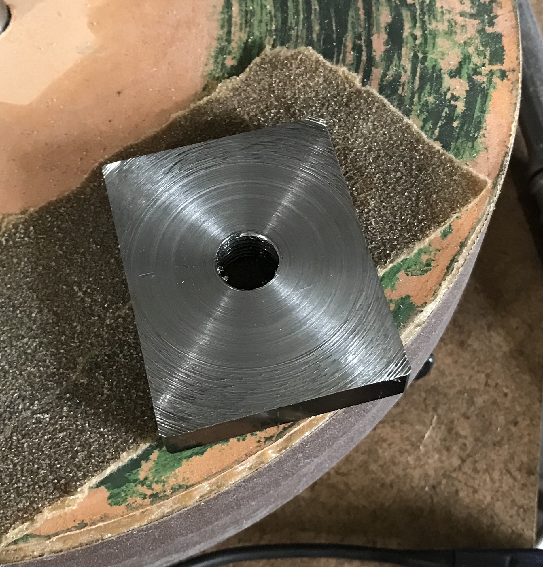
The plate was held in the four jaw chuck using parallels to even it up. There was a lot of chatter as expected. The carriage lock had to be tightened to keep the carriage still. The plate was thinned to 0.426" and can be seen below. I decided not to remove the 0.3" from each side. Too much chatter. A better approach is cutting off one side with the band saw. Measure from the opposite side and bring down the appropriate amount with the mill. This side then becomes the reference for the other side.
Since the mill is tied up with the unfinished gear for the business card, the next cuts were performed on the South Bend lathe. The bandsaw was used to remove 0.25" from one side. The block was held in the four jaw chuck and aligned with a drill. Steel was removed in 0.005" passes until the size was correct. The other side was cut off with the bandsaw and then milled until the final size was 1.25". The chatter was manageable.
I am going to attempt cutting the rabbets for the T slot on the shaper. I want to try slower cutting and see if that improves the finish.
Don't know why this popped into my head, but I decided to try a quick experiment on taking stereo photos. I sat my camera on a tissue box and took two pictures about an inch apart focused on a point 12" away, about 5°. I could not cross my eyes to get the stereo effect, but the black stereo VCH viewers worked fine! Editing the photos so they are narrower was necessary, or so I think for the crossed eyes, but it might not be needed for the viewers.
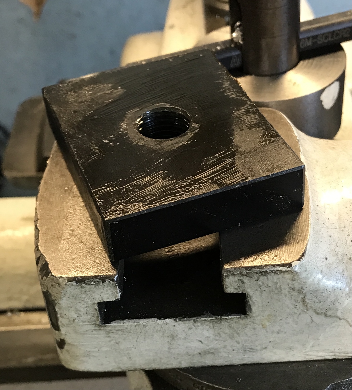
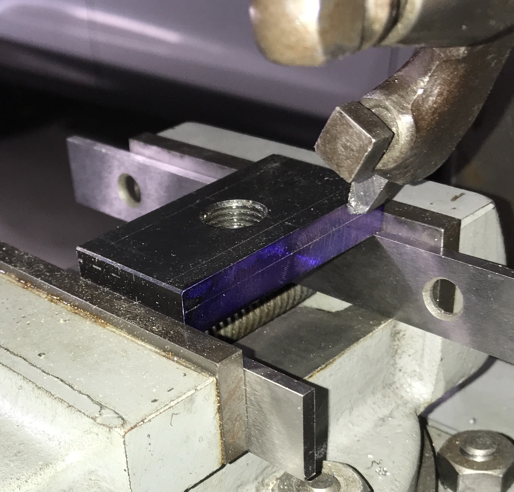
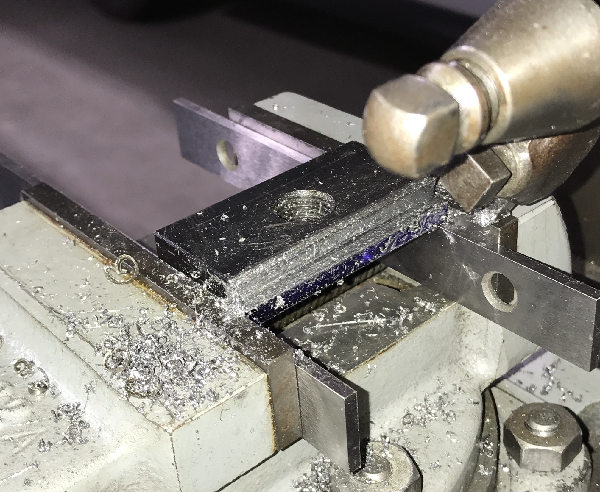
Back to the base plate. This afternoon was shaper time. The part was marked out at 0.175" down and 0.200" in. The steel was set up on parallels in the shaper vise. It was set down with a rubber mallet, so the parallels were tight. There was a lot of difficulty at first with wildly varying cutting depths that changed during a cut. Realization finally arrived and the vertical adjustment knob was tightened. Both nuts needed tightening. The shaper performed much better and 0.010" cuts were made with the horizontal movement set at about 0.005". It was difficult to tell how far the cut proceeded. The dimensions were taken and the bottom was cut to 0.175" depth. The part was turned in the shaper so an edge was up. This side was lowered to 0.200". There is still a lot of material in the corner. This will be tackled tomorrow.
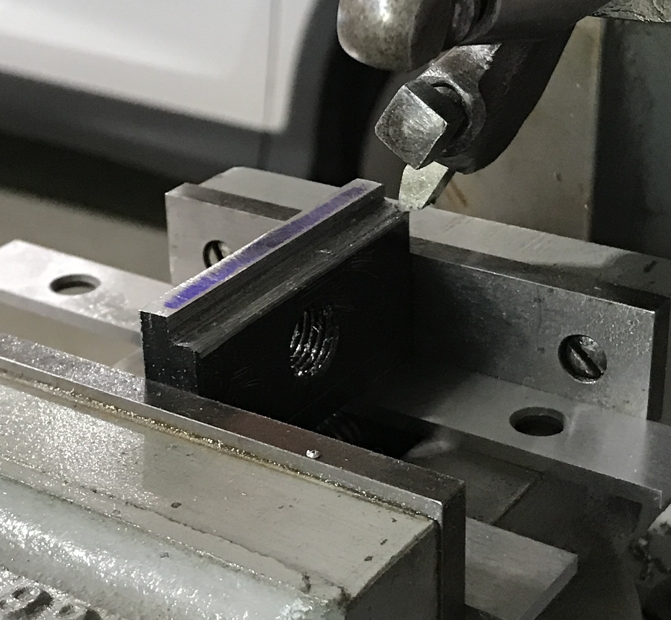
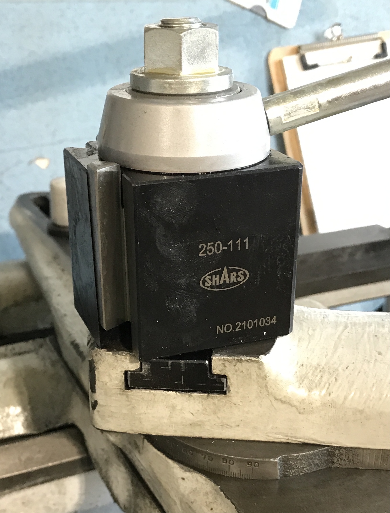
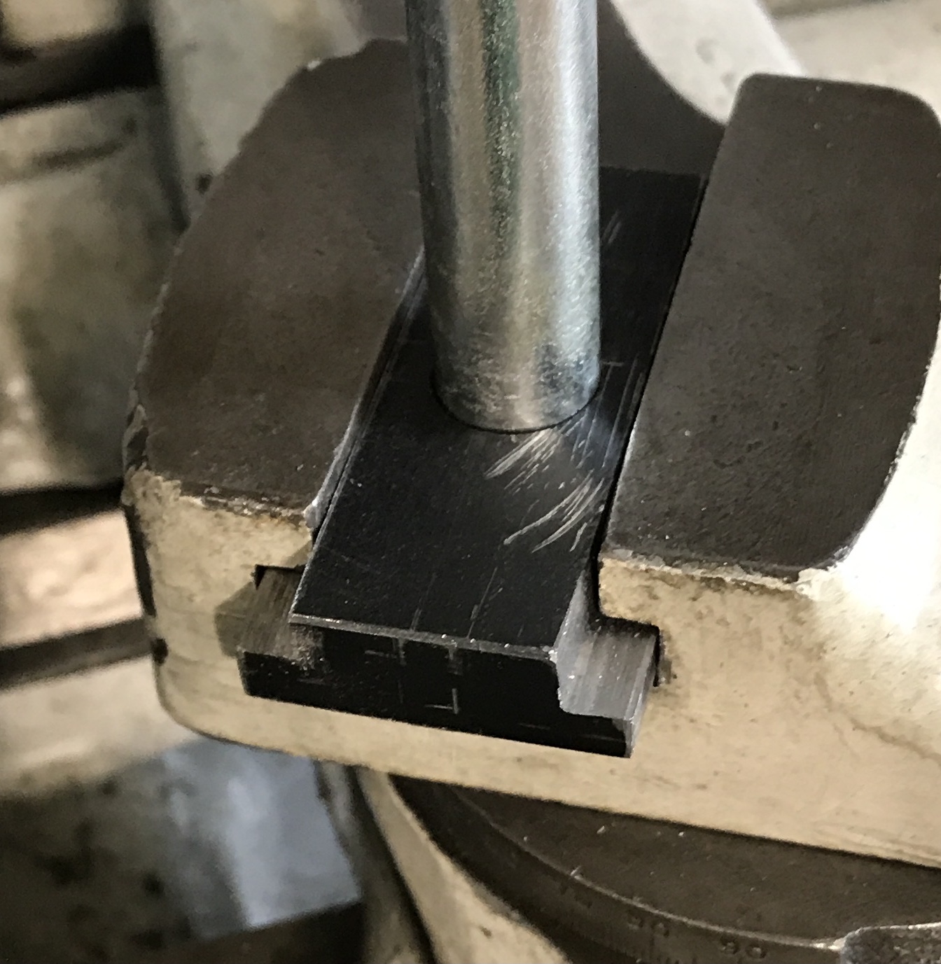
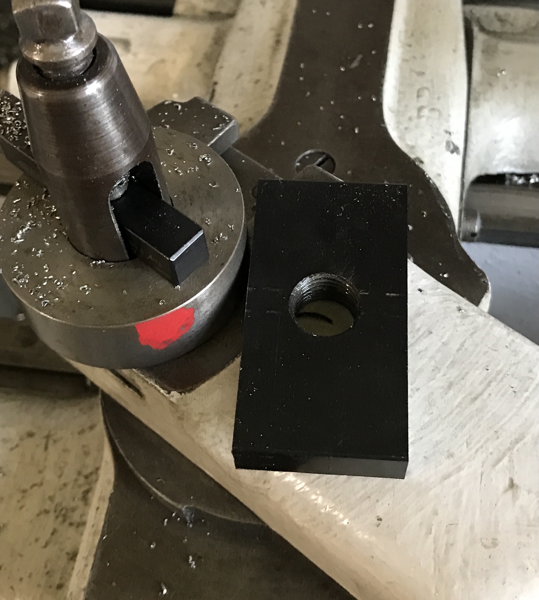
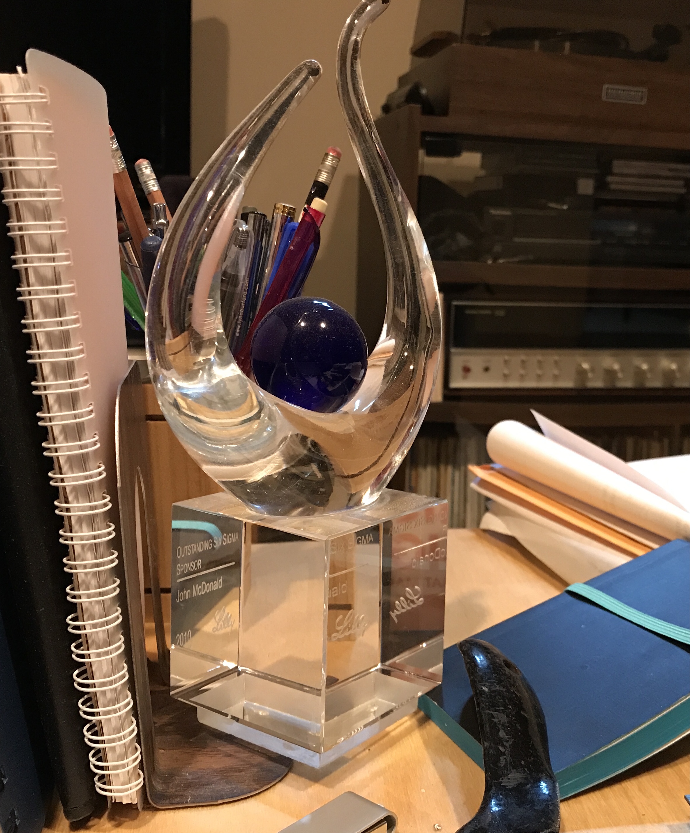
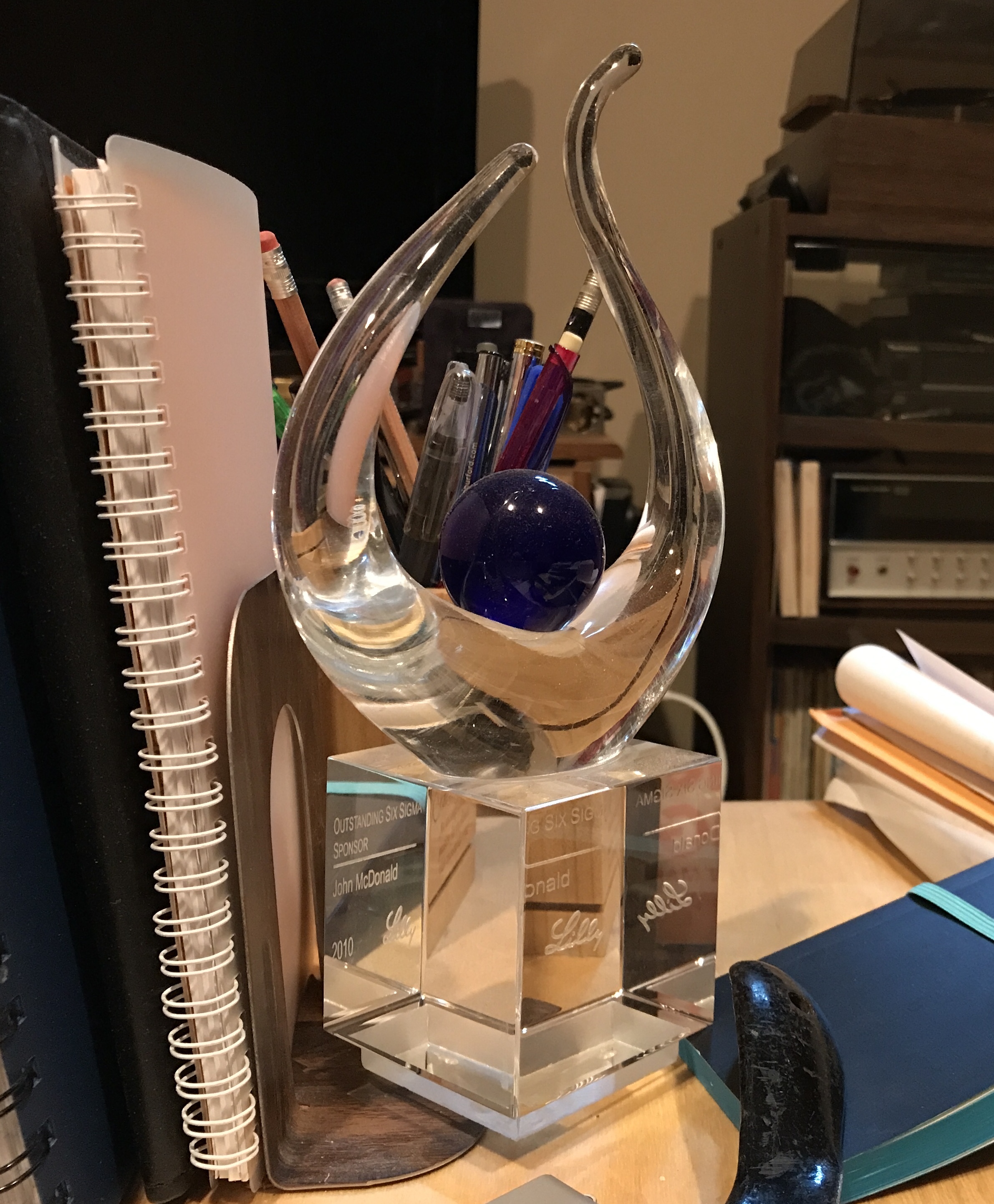
After some more work on the shaper the base plate looked pretty good as seen in the first photo below. What the photo does not show is that the base does not fit. It was too wide at the narrow top. Much of this problem was due to an insufficiently deep cut on one side. This was rectified with a lot of filing. Now the fit is very good. The last two pictures show the plate in place.